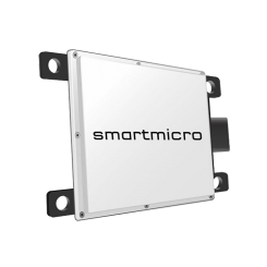
smartmicro automotive radar UMRR-11 Type 132
The smartmicro automotive radar UMRR-11 4D/HD is a high definition, multi-object tracking traffic radar and features 4D/HD capabilities.
The sensor is a small, lightweight, very robust low-cost 76GHz radar for automotive applications. It is intended for multiple applications and can be used almost worldwide in this frequency band.
It works in adverse conditions, almost unaffected by weather, and independent of sunlight, in a wide temperature interval. The radar withstands high shock and vibration levels are maintenance free and made for a long lifetime.

Features
- Operation at the 77GHz band
- Small, lightweight, very robust
- Works in adverse conditions
- Short- and medium range collision warning
- Best-in-class antenna technology
- Patented high-speed modulation technique
- CAN bus, 100MBit Ethernet and full duplex RS485 interface
- Buffered real time clock
- 3D attitude sensor (measures pointing angle of the sensor)
- 3D acceleration sensor
Platform Antenna Type 132
General sensor performance data
| Parameter | Long-Range Mode | Medium-Range Mode | |
|---|---|---|---|
| Operating Frequency | 76…77GHz 4 center frequencies (bands) |
76…77GHz 2 center frequencies (bands) |
|
| Range1 | Min./Max.2 | 1.0m/175m | 3ft/574ft | 0.5m/64m | 1.6ft/210ft |
| Separation | ≤ 1.8m | ≤ 5.9ft | < 0.66m | < 2.17ft | |
| Accuracy | < 0.5m | < 1.64ft or 1% (bigger of) | < 0.25m | < 0.82ft or 1% (bigger of) | |
| Velocity | Min/Max | -400…+200km/h | -248…+124mph | -340…+170km/h | -211…+105mph |
| Separation | < 0.26m/s | < 0.26m/s | |
| Accuracy | ≤ 0.1m/s | ≤ 0.1m/s | |
| Angle | Field of View: Azimuth3 | -16…+16° (narrow beam) | -50…+50° (wide beam) |
| Field of View: Elevation3 | -7.5…+7.5° | -7.5…+7.5° | |
| Separation: Azimuth | 4° (optional) | 15° (optional) | |
| Accuracy: Azimith4 | ≤ 0.25° | ≤ 0.5° | |
| Accuracy: Elevation4 | ≤ 0.5° | ≤ 0.5° | |
Mechanical details
| Weight | ≤ 274g | ≤ 9.67oz |
|---|---|
| Dimensions (H × W × D) | 94.7mm × 84.4mm × 26.4mm (plus connector) |
Further information
| Initialization Time | < 4s |
|---|---|
| Update Cycle Time | ≤ 55ms |
| Processing Latency | 2-4 cycles |
| Operating Voltage5 | 8…32V |
| Power Consumption6 | < 5W |
| Bandwidth | < 1000MHz |
| Max. Transmit Power (EIRP) | < 35dBm |
| Operating & Storage Temperature | -40…+85°C | -40…+185°F |
| Interfaces7 | Ethernet 100Mbit (4-wire); 1xCAN V2.0b (passive); 1xCAN FD (optional) |
| Connector | Hirose LF10 series |
| Shock / Vibration | 100 grms / 14 grms |
| Relative Humidity | 0…95% (non-condensing) |
| IP | 67 |
| Pressure or Transport Altitude | 0…10000m | 0…32800ft |
1 Optionally, the minimum range can be reduced for customer-specific needs that depend on local frequency regulations. ↩
2 Typical values; all values given for bore sight; they may vary depending on the clutter environment. Please note that the radar system can neither achieve a detection probability of 100% nor a false alarm rate equal to zero. ↩
3 The total field of view is an angle interval in which reflectors can be detected; 3dB field of view is narrower. ↩
4 The typical value is measured at a target output level at bore sight, for a point reflector showing >23dB SNR. Errors may increase towards larger angles. ↩
5 Measured at the connector. ↩
6 Power consumption at 20°C. ↩
7 It is recommended to use an external surge protection for power, CAN, RS485, Ethernet and other interface ports. ↩